Synopsys Design Compiler Tutorial 2021 May 2026
Synopsys Design Compiler Tutorial (2021 Edition): A Comprehensive Guide to Logic Synthesis
Introduction
Synopsys Design Compiler (DC) remains the gold standard for logic synthesis in the semiconductor industry. Even in 2021, while many teams transitioned to the topographical and Explorer variants, the core DC shell remains the heartbeat of RTL-to-Gates design flow. It translates Register Transfer Level (RTL) code (Verilog or VHDL) into gate-level netlists optimized for timing, area, and power constraints based on a specific technology library.
This tutorial provides a comprehensive walkthrough of the synthesis flow using Design Compiler, focusing on the methodologies, constraints, and optimization techniques relevant to modern design flows.
Target library (logic gates)
set target_library "tcbn28hpc.db"
Invocation
Launch the tool via the Common UI (recommended for tutorials):
dc_shell -gui
Alternatively, use the command-line mode for batch scripts:
dc_shell -f run_synthesis.tcl | tee synthesis.log
❌ Cons
- Assumes basic Tcl knowledge – Beginners without Tcl scripting experience may struggle with variables, loops, and proc usage.
- Limited physical design context – Focuses only on logic synthesis; no mention of floorplanning or back-end flow (e.g., ICC2/Innovus interaction).
- Sparse on advanced topics – Little coverage of multi-mode multi-corner (MMMC), UPF low-power flow, or advanced retiming.
- No license or tool access – As with most vendor tutorials, you need your own Synopsys license – no cloud sandbox provided.
- Minor outdated examples – Some 2021 scripts may use older
.libformats; modern process nodes (5nm/3nm) not discussed.
Basic Compile Flow:
# Set operating conditions (worst case for setup)
set_operating_conditions -max "WCCOM" -max_library $target_library
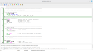
Step 1: Launching the Tool
Open a terminal and invoke the GUI or shell mode.
dc_shell -gui
Pro tip for 2021: Use dc_shell -64bit -legacy_ui if you prefer the classic Tcl prompt over the new Python-driven interface.
6.2 Area Report
This summarizes the total cell area.
report_area -hierarchy
8. Example Output (Snippet)
After successful synthesis, you should see:
Beginning Pass 1 Mapping ...
Processing clock clk (period 10.00)
Optimization completed
Total mapping time: 0:00:12
***********************************************************************
Final Area: 12543.2 um^2
Final Worst Negative Slack (WNS): 0.12 ns
Final Total Negative Slack (TNS): 0.00 ns
***********************************************************************
End of Tutorial Text
Note: For the most accurate 2021 behavior, refer to the official dc_shell user guide: dc_ug.pdf (version M-2017.03-SP3 through 2021.09). synopsys design compiler tutorial 2021
The Synopsys Design Compiler (DC) remains the industry standard for logic synthesis, acting as the critical bridge between Register Transfer Level (RTL) code and a physical, gate-level netlist . As of the 2021 era, the toolset includes Design Compiler NXT
, which introduced faster optimization engines and highly accurate RC estimation for advanced nodes like 5nm and below. The Synthesis Flow: From RTL to Netlist
The fundamental goal of Design Compiler is to transform high-level hardware descriptions (Verilog, SystemVerilog, or VHDL) into a technology-specific gate-level representation. This process is governed by four primary stages: ASIC Design Flow Tutorial Using Synopsys Tools
Mastering Digital Synthesis: A Synopsys Design Compiler Tutorial (2021 Edition)
In the world of VLSI, Synopsys Design Compiler (DC) remains the industry standard for logic synthesis. Whether you are a student or a professional engineer, mastering DC is essential for transforming high-level RTL (Verilog/VHDL) into an optimized gate-level netlist.
This 2021 tutorial focuses on the modern Topographical Mode and the core commands needed to navigate the synthesis flow effectively. 1. Understanding the Synthesis Flow
Synthesis is not just "translating" code. It is an optimization process that balances the PPA trinity: Power, Performance, and Area. The basic workflow involves:
Translation: Converting RTL to an unoptimized boolean representation (GTECH).
Optimization: Mapping GTECH to specific cells from your Target Library.
Mapping: Finalizing the gate-level netlist based on constraints. 2. Setting Up Your Environment
Before launching DC, you must define your library paths. This is typically done in a .synopsys_dc.setup file in your home directory or project folder. Target library (logic gates)
set target_library "tcbn28hpc
# Setup Variables set link_library "* standard_cell_lib.db" set target_library "standard_cell_lib.db" set symbol_library "standard_cell_lib.sdb" set search_path ". /path/to/libraries /path/to/rtl" Use code with caution.
Target Library: The physical cells the tool will use to build your design.
Link Library: Used to resolve references (e.g., pre-existing IP blocks or pads). 3. Loading the Design
You can use read_verilog or the modern analyze and elaborate flow. The latter is preferred as it allows for better error checking and parameter passing.
# Analyze the RTL (Checks for syntax) analyze -format verilog my_design.v sub_module.v # Elaborate (Builds the generic technology-independent design) elaborate my_design # Set the current design context current_design my_design Use code with caution. 4. Applying Constraints (The SDC File)
Design Compiler is "constraint-driven." If you don't tell it how fast the design should be, it won't optimize for speed. These are typically saved in a Synopsys Design Constraints (SDC) file. The Clock:
create_clock -name my_clk -period 10 [get_ports clk] set_input_delay 2.0 -clock my_clk [all_inputs] set_output_delay 1.5 -clock my_clk [all_outputs] Use code with caution. Design Environment:
set_max_area 0 ;# Tells DC to make the design as small as possible set_load 0.5 [all_outputs] Use code with caution. 5. Running Compilation
In 2021, most designs use Design Compiler Graphical or Topographical mode. This mode uses physical data (like floorplan info) to predict wire delays more accurately than the old "Wire Load Models."
# Basic compile compile # For better results in modern nodes (Topographical) compile_ultra Use code with caution.
compile_ultra performs high-effort optimizations, including register retiming and advanced arithmetic optimization. 6. Analyzing Results (Reporting) Alternatively, use the command-line mode for batch scripts:
Once the synthesis is finished, you must verify if your constraints were met. Timing: report_timing (Check for Setup/Hold violations). Area: report_area (Check gate count and physical size). Constraint Violations: report_constraint -all_violators. 7. Exporting the Netlist
The final output is a gate-level netlist and an updated SDC file, which are then passed to Place and Route (P&R) tools like IC Compiler II.
write -format verilog -hierarchy -output "my_design_netlist.v" write_sdc "my_design_final.sdc" Use code with caution. Pro-Tips for 2021 Synthesis:
Check for "Unresolved References": Always run link after elaboration to ensure all modules are found.
Avoid "Dont_Touch": Be careful using set_dont_touch on modules, as it prevents DC from optimizing across boundaries.
Check Design: Use check_design before compiling to find unconnected wires or multiple drivers.
By following this flow, you can ensure that your RTL is transformed into a robust, high-performance netlist ready for physical implementation.
Do you have a specific RTL module or library file you're trying to synthesize right now?
Here’s a balanced review of a typical “Synopsys Design Compiler Tutorial 2021” (assuming a standard university or online technical tutorial based on the 2021 version):
Load capacitance (Fan-out estimation)
set_load 0.05 [get_ports data_out*]